Start / Project History and Status / Project History
Project History

How the project developed over time.
Oktober 2012
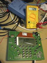
During bring-up a number fo new test functions where coded to test the other boards in an efficient way. Some assembly changes where found to adjust voltages and crystal frequencies to the projected values. A PCB error within the step regulator is easy and reliable to repair. By the beginning of November the first eight systems were in the process of completion and bring-up.
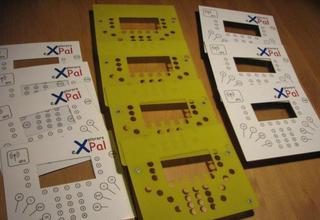
The first lot of eight front plates was also completed by the end of October.
September 2012
Thomas received 30 assembled PCB's and front plates.
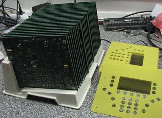
The bring-up work starts with power supply sub circuits. Step by step the remaining pards are added to the first system.
August 2012
We collected the material stock within the projet team and delivered everything to Dresden Elektronik. To be safe, a reflow oven test for the chinese custom height buttons was scheduled...
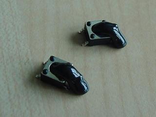
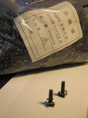
... and saved us from loosing lots of buttons and manufacturing line trouble. The original shape of the button can be seen in the February 2011 entry. We'll have to assemble the buttons manually.
July 2012
The final part delivery is now dated for the end of August. Manufacturing will happen in September after the summer break.
June 2012
The financing for the PCB assembly could be settled. The remaining system material, the GPS module and any kind of tools for the firmware development is not covered by the sponsoring. For most of the system material we could collect a little stock.
April 2012
After all individual material requests have been aswered we could estimate the cost as follows:
Material for SMT assembled circuit boards: about EUR 55,- per unit
Material for milled front plates: about EUR 8,50 per unit
One time cost for PCB and SMT paste mask: about EUR 350,-
Remaining material to complete the system: about EUR 40,- per unit
GPS module: EUR 26,- to 29,- each, depending on the type
In the hope of sponsoring we did not determine the manufacturing costs (yet).
February 2012
A preliminary set of manufacturing data has been transfered to Dresden Elektronik to get the manufacturing costs estimated.
December 2011
Schematic and PCB design are almost done. The new circuit parts have been tested in simulation and as a wire wrap build-up. Considering our stock of 30 displays, the next run should produce 30 systems. The financing will not work out without sponsoring. To get everything in place, the exact material costs need to be determined first.
October 2011
Holger and Thomas visit the open seamap developers during thair meeting near Nuremberg (Germany).
September 2011
Thomas did some investigations and simulations for the new SD card power regulator. We can consider the controller supply as regulated already. Therefore a cheap solution can be found with an op amp, a transistor and some passive parts. More simple solutions can be found online using an LED or a single zehner diode. However, they either act to weak, consume excessive current or do not work well over a wide temperature range.
The Simulationschematic shows the solution for eXplorers Pal. For the sake of the simulation, the output is loaded with a current pulse (from I1) as it occures during a SD access. Transistor Q1 regulates the output voltage. The diodes shift the base voltage into a range that can be handled by a cheap non R2R op amp. The output voltage is controled by U1A and regulated to the value adjusted with R2/R3.
The output current is measured through R4 as a shunt. U2A compares the value with the trigger value adjusted by R6/R8. For currents above 4mA the LED is activated.
August 2011
In August we did initial attempts to create a tiny file download tool for windows using python and tkinter. Well, it works but still requires a cooperative user. So, still room for improvements :-).
July 2011
While doing software development work as well as field tests, a nuber of hardware issues became visible. It does not make sense to build more systems with the current hardware. In detail, the following issues have to be solved:
- Independant power supply for GPS module and SD card
- The SD power consuption controled access indication turned out to be a neat feature
- Changed SRAM address start at 0x8000
- State of the art low power SRAM parts are not available in SO or SOJ packages. Have to change to TSSOP.
- more details like eg. a piezo buzzer
On the hardware side we will proceede with a redesign.
April
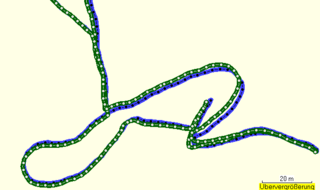
In order to evaluate the GPS data quality, we have tested eXplorers Pal against a Garmin 60CSx device. The picture below shows the 60CSx track in green and the prototype #4 track in blue. The data acquisition was done under good sky view conditions. It shows access ways and the surroundings of a rain water reservoir.
March 2011
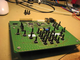
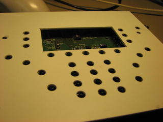
Prototype #2 has to give up his old keys and is equipped with new 14mm keys. The manually drilled front panel seems to fit so far.
Februar 2011
To construct a system with front panel, a key hight of 14mm is required. In spite of a long search, there where no off the shelve keys with more than 12mm hight. The existing solution consisting of a key and a key head did also add more than 20 cent per key to the bill of material. Thomas did contact a manufacturer in China to get customized keys built. The bag with the initial 1000 keys arrived in early March.
January 2011
Prototype #4 and #5 running.
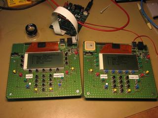
December 2010
Prototype #4 is alive, for #5 some remaining parts are on order.
Holger and Thomas had a meeting to join the software for timer and power management.
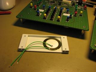
Beginning with prototype #4 a piezo disk will is installed underneath the display.
November 2010
POI Menu and prototype #4 and #5 assembly:
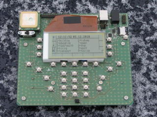
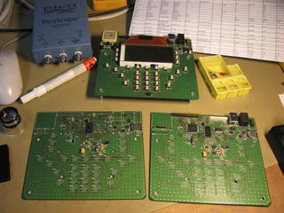
October 2010
Some pictures: (GPS status and house number logging)
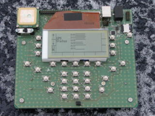
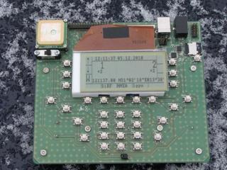
September 2010
Holger creates a build and configuration system based on automake, autoconf & Co.
Thomas is generating web content using the JAC Systeme CMS server.
Sebastians POI logger is showing initial live signs. We need an alphanumerical text editor.
August 2010
Sebastian demonstrates his first version of a user interface making use of soft keys also.
A main element is the switching in between several apps. A new app for POI logging is also evolving.
The power management goes beta.
Juli 2010
Software, Software, Software and Software.
JAC Systeme offers to host a web site for us.
Juni 2010
The eXplorers Pal developers met in Zittau (Germany).
Everybody is pushing forward his software.
Mai 2010
Holger is doing the first field try of the house number logging application.
Thomas is busy with the power management system. The key scan had to be written new to implement a solid power management. Key activity has now a clear interaction with the power state control .
April 2010
A new software patch allows to receive NMEA data from an external interface. This helps a lot for indoor debugging, when recorded NMEA data can be sent from a PC.
Sebastian did contribute an OS module to store data within the ATmega EEPROM.
Holger is working to get the GPS-Module binary mode up and running. There are some interesting control commands documented that we like to use for the power management.
Thomas was in contact with a mechanical design engineer to find a solution for the housing.
March 2010
First long term data logging test did show an operating time of 40 hours with 2850mAh rechargable batteries. This result was achieved without much power saving. It is likely that we get a considerable longer operating time when power saving is ready to use.
In March Sebastian joined our little project and installed the bugtracking system. Prototype number III was built for him and we did extend our display stock by 30 parts. This will give us some more room to work with this board design.
February 2010
SD Card bring-up was successfull. Reading and writing to FATFS is working now. NMEA Data from the GPS module can also be processed. This test outdoor in the snow did also prove that the LCD can handle the low temperature.
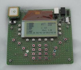
January 2010
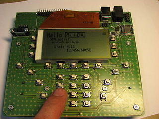
The display is now savely mounted on an ABS carrier. We have two identical prototypes running for Thomas and Holger. We already bouhgt the Material stock for three more systems. It's ~EUR 100,- per prototype.
LCD Library, USB and key scan is working well.
The domain www.explorerspal.org went online.
December 2009
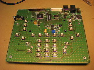
The board assembly is complete, the main functions are tested and we can get the display up and running.
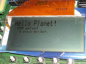
The display is only isolated with some card board and some tape is keeping it in place.
November 2009
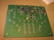
The parts are complete and five bare boards returned from the factory. First step was the power supply bring up, the micro and the peripherals did follow.
August 2009
Thomas did start the design work at the first single board system.
June 2009
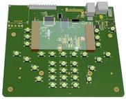
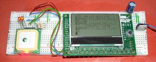
Holger started working at basic software routines with a GPS module and an ATMEL DB101 board
April 2009
The idea was born to design a special device for the mobile logging of house numbers. It should be separated in a left and a right section to represent locations to the left and right side of the road.
